
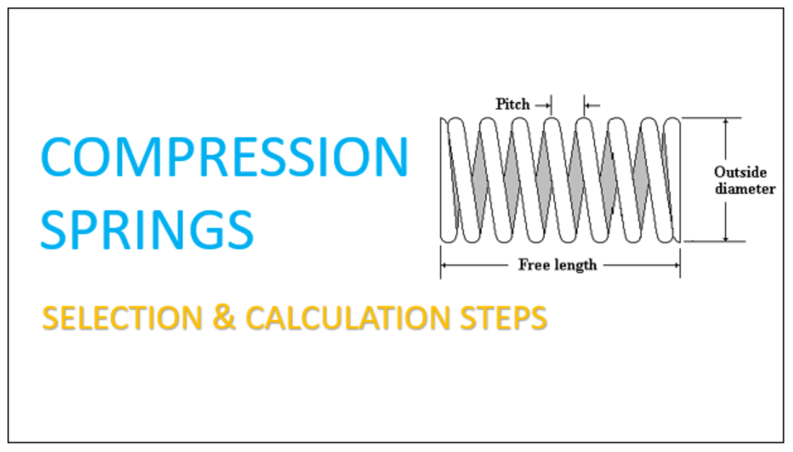
Hello everyone, Welcome to ELearnInsight.
You might have seen different springs in your day-to-day life. The compression spring is also amongst them. Let’s take a look at compression springs. So compression springs sit inside thousands of everyday products. They push back when you press a pen. similarly absorb shock in a car suspension. Also, they hold a valve shut in a hydraulic system. Yet many engineers still pick a spring by guesswork instead of calculation. Moreover, this habit causes premature failure, wasted material, and expensive redesigns.
Eventually this blog guide walks you through a complete compression spring selection process. Firstly, you will learn the key design parameters. Later, you will follow a clear, step-by-step selection method. Then, you will see the core formulas used in real spring calculations. Finally, a worked example ties every formula together so you can apply the same process to your own project.
Whether you are a student learning spring mechanics, a design engineer sizing a new component, or a procurement professional verifying a supplier’s spec sheet, this guide gives you a repeatable, accurate process for compression spring selection and calculation—anywhere in the world.
What Is a Compression Spring?
A compression spring is a helical coil that resists a squeezing force. Unlike an extension spring, it pushes apart instead of pulling together. When you apply a load along its axis, the coil compresses and stores mechanical energy. Then once you release the load, the spring pushes back and returns toward its free length.
So, engineers use compression springs in suspension systems, valves, switches, mattresses, and countless industrial machines. Because the design space is so wide, no single spring fits every application. Therefore, a structured selection process matters far more than intuition.
Key Parameters You Must Define First
Before you calculate anything, gather these parameters. Each one directly drives the final spring rate and stress calculation.
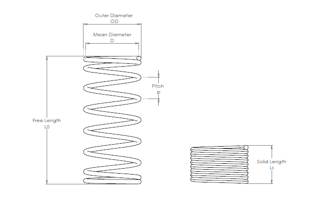
- Wire diameter (d): the thickness of the wire used to wind the coil.
- Outer diameter (OD): the outside measurement of the coil.
- Mean diameter (D): measured to the wire’s centre line; D = OD − d.
- Free length (L0): the spring’s length with no load applied.
- Solid height (Ls): the length when every coil touches, at maximum compression.
- Active coils (Na): the coils that actually flex under load.
- Total coils (Nt): all coils, including inactive end coils.
- Spring index (C): the ratio of mean diameter to wire diameter, C = D / d.
- Material and shear modulus (G): defines stiffness and fatigue behavior.
Collect these numbers early. They feed directly into every formula in the sections that follow.
Step-by-Step Compression Spring Selection Process
Step 1: Define the Working Load and Travel
Initially, start with your application, not a catalog. Ask how much force the spring must exert as well as over what distance it must travel. For example, a push-button spring might need 50 N of force at 12 mm of compression. Record both the minimum and maximum load points, since most springs work between two deflection limits, not just one.
Step 2: Set the Space Envelope
Then, measure the available space. Note the maximum outer diameter, the minimum inner diameter if the spring rides on a rod, and the maximum free length. These physical limits narrow your material and coil options before you run a single formula.
Step 3: Choose the Spring Material
After that, pick a material based on the operating environment. Furthermore, music wire (ASTM A228) suits general-purpose, high-strength springs. Additionally, stainless steel (302 or 316) resists corrosion in humid or chemical environments. Chrome silicon and chrome-vanadium alloys handle high stress and elevated temperature. Each material has its own shear modulus (G) and tensile strength, so this choice affects every later calculation.
Step 4: Calculate the Required Spring Rate
Furthermore, now apply Hooke’s Law to find the spring rate you need. Later divide the change in load by the change in deflection: k = F / x. Then this target spring rate becomes the benchmark for the geometry calculations in the next step.
Step 5: Size the Wire Diameter and Coil Geometry
However, using the spring rate formula, solve for wire diameter, mean diameter, and active coils together. Because the formula has several unknowns, engineers typically fix one variable — usually the spring index, ideally between 4 and 12 — and solve for the rest. A spring index below 4 is hard to manufacture. An index above 12 tends to tangle and buckle under load.
Step 6: Check Solid Height and Clearance
Verify that the solid height fits within your available space, even under maximum load. Also confirm the spring never fully bottoms out during normal operation. As a rule of thumb, keep 10 to 15 percent clearance between the operating height and the solid height.
Step 7: Verify Stress and Fatigue Life
Calculate the maximum shear stress in the wire, then compare it against the material’s allowable stress. For springs that cycle repeatedly, keep working stress below 45 percent of the minimum tensile strength (MTS). This margin protects the spring against fatigue failure over its service life.
Step 8: Select End Type and Finish
Finally, choose an end configuration: plain, plain-and-ground, squared, or squared-and-ground. Ground ends sit flatter and distribute load more evenly, which matters in precision assemblies. Add a protective finish, such as shot peening or plating, if the spring faces a corrosive or high-cycle environment.
Step 9: Prototype and Test
Once the calculation is complete, build a prototype. Measure the actual spring rate under load, and compare it against your target. Small variations are normal because of manufacturing tolerances, so always validate before committing to full production.
Compression Spring Calculation Formulas
These are the core equations behind every compression spring calculation. Use them together, not in isolation, since each variable depends on the others.
| Quantity | Formula | Notes |
| Spring rate (k) | k = G·d⁴ / (8·D³·Na) | Stiffness of the spring; force per unit deflection. |
| Load (F) | F = k · x | Hooke’s Law: x is deflection from free length. |
| Spring index (C) | C = D / d | Keep between 4 and 12 for manufacturability. |
| Wahl factor (Kw) | Kw = (4C−1)/(4C−4) + 0.615/C | Corrects for coil curvature and direct shear. |
| Max shear stress (τ) | τ = 8·F · D · Kw / (π·d³) | Compare against allowable stress for the material. |
| Solid height (Ls) | Ls = Nt · d | Height when all coils touch. |
| Total coils (Nt) | Nt = Na + 2 | Typical for squared-and-ground ends. |
Worked Example: Step-by-Step Calculation
Let’s size a compression spring for a mechanical push-button assembly. This example follows the exact process outlined above, so you can reuse it for real-time spring selection on your own project.
Given Requirements
| Given Requirement | Value |
| Working load, F | 50 N at full deflection |
| Deflection, x | 12 mm |
| Maximum allowed OD | 12 mm |
| Material | Music wire, ASTM A228 (G = 79,300 N/mm²) |
| End type | Squared and ground |
Calculation Steps
1. Required spring rate:
First we will define the required spring rate.
k = F / x
= 50 N ÷ 12 mm
= 4.17 N/mm.
2. Trial wire diameter and index:
Then we will define wire diameter and spring index.
Choose d = 1.2 mm and C = 7.
So, D = C × d = 8.4 mm
and OD = D + d = 9.6 mm.
This fits within the 12 mm limit.
3. Solve for active coils:
Later we will solve for active coils.
Na = (G × d⁴) / (8 × D³ × k)
= (79,300 × 2.0736) / (8 × 592.7 × 4.17) ≈ 8.3 coils.
Round to 8.5 for a clean squared-and-ground design.
4. Recalculate actual spring rate
Now we need to recalculate the actual spring rate.
with Na = 8.5:
k = (79,300 × 2.0736) / (8 × 592.7 × 8.5)
≈ 4.08 N/mm — close to the 4.17 N/mm target.
5. Total coils:
The Next task is to define total coils
Nt = Na + 2
= 10.5 coils (squared and ground adds one inactive coil per end).
6. Solid height:
Also define a solid length
Ls = Nt × d
= 10.5 × 1.2 mm
= 12.6 mm.
7. Free length:
Moreover, for free length.
Allow the operating deflection (≈ 12.25 mm at 50 N) plus about 15% clearance to the solid.
Free length L0 ≈ 27 mm, which leaves roughly 14.9% clearance above solid height.
8. Wahl correction factor:
Next we will find the Wahl correction factor.
Kw = (4×7 − 1)/(4×7 − 4) + 0.615/7
= 27/24 + 0.088 ≈ 1.213.
9. Maximum shear stress:
later for maximum shear stress
τ = (8 × F × D × Kw) / (π × d³)
= (8 × 50 × 8.4 × 1.213) / (π × 1.728) ≈ 751 MPa.
10. Stress check:
Finally, the stress check. Music wire at 1.2 mm typically has an MTS near 2,170 MPa. The 45% allowable limit is about 977 MPa. Since 751 MPa is below that limit, the design passes with a margin for cyclic loading.
Final Calculated Spring
| Calculated Property | Result |
| Wire diameter, d | 1.2 mm |
| Spring index, C | 7 (D = 8.4 mm, OD = 9.6 mm) |
| Active coils, Na | 8.5 coils |
| Total coils, Nt | 10.5 coils |
| Actual spring rate, k | ≈ 4.08 N/mm |
| Solid height, Ls | 12.6 mm |
| Free length, L0 | 27 mm |
| Wahl factor, Kw | 1.213 |
| Max shear stress, τ | ≈ 751 MPa |
| Allowable stress (45% of MTS ≈ 2170 MPa) | ≈ 977 MPa — design passes |
As a result, this spring meets the load, travel, space, and fatigue requirements. You can now issue it as a drawing spec or check it against a manufacturer’s stock catalog.
Common Mistakes to Avoid
- Ignoring the spring index range—an index outside 4–12 causes manufacturing and stability problems.
- Skipping the solid height clearance check—the spring bottoms out, and load-deflection behavior turns nonlinear.
- Using yield stress instead of the 45% MTS guideline for cyclic, high-fatigue applications.
- Forgetting the Wahl correction factor — this understates real shear stress, especially at low spring indices.
- Using a generic shear modulus instead of the value for the actual selected material and wire diameter.
- Skipping prototype testing — calculated and measured spring rates can differ due to tolerances.
Market Availability
However, it is not always mandatory to design a new spring or use a custom spring for your application. Because in the market there is availability of standard springs on the basis of load and application. Special Springs, Misumi, ASRaymond, and IEM, as well as Dayton, are standard ISO and JIS spring providers in the market.
Conclusion
Finally, correct compression spring selection combines application requirements, material science, and geometric calculation. Follow the nine-step process above, apply the core formulas, and validate every design with a prototype. This structured approach, rather than trial and error, delivers a spring that performs reliably across its full service life—whether you build one prototype or specify thousands of units for global production. To sum up, it is always a great idea to create your design according to market standard availability.
Disclaimer: Some content in this blog is generated from the AI for informational purposes only.
Nice content
Could you please write how to improve spring life.